Instax SQ1 disassembly: teardown in 10 steps
How to strip a Fujifilm Instax SQUARE SQ1 down to its chassis, film transport and eject motor. This is Part 1 of the guide for the Square67 adapter, which turns the SQ1 into an instant back for the Mamiya RB67. The lens, main board and flash come out; everything that moves the film stays.
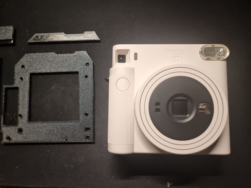
Irreversible. This modification is permanent. The camera loses its own lens, flash and warranty.
Safety first
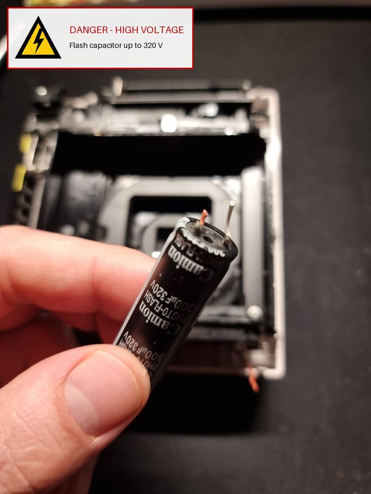
The flash capacitor (300 µF, 320 V) can hold a dangerous charge long after the batteries are removed. Discharge it before you touch its leads or the flash board.
- Remove both CR2 batteries and any film pack before you start.
- Discharge the flash capacitor through a resistor (e.g. 1–10 kΩ, 2 W or more) held with insulated pliers. Do not short it with a screwdriver.
- Measure the voltage across the capacitor terminals with a multimeter; continue only when it reads close to 0 V.
- Work on an anti-static mat if possible; the main board is sensitive to static discharge.
- Wear safety glasses when cutting wires and prying plastic clips.
Tools and materials
| Item | Used for |
|---|---|
| Precision Phillips screwdriver (PH00 / PH0) | All housing and chassis screws |
| Thin plastic card (old payment or loyalty card) | Releasing the clips of the film-exit cover |
| Plastic spudger or guitar pick | Separating the front and rear shells |
| Flush side cutters | Cutting capacitor and battery leads |
| Soldering iron, solder wick, flux | Desoldering wires from the main board |
| Fine tweezers | Freeing wires from their routing channels |
| Resistor 1–10 kΩ / 2 W + multimeter | Discharging and checking the flash capacitor |
| Small labelled containers or a magnetic tray | Keeping screws sorted by step |
Tip: photograph each stage before you remove anything. Screws differ in length between steps, so keep them in separate labelled compartments.
Part 1 – Disassembly
Step 1 – Check the kit and prepare the camera
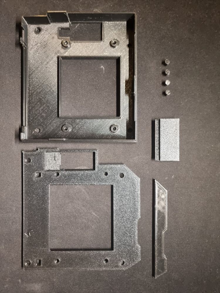
Lay out the printed adapter parts and the SQ1 before you start. Remove the batteries and the film pack, and close the battery and film doors.
Step 2 – Remove the outer housing screws
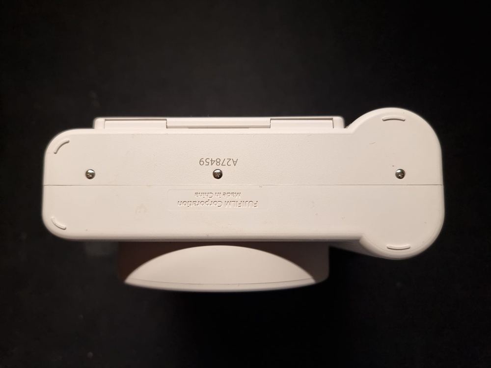
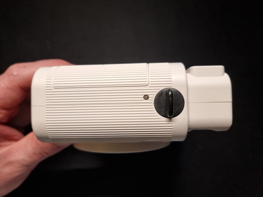
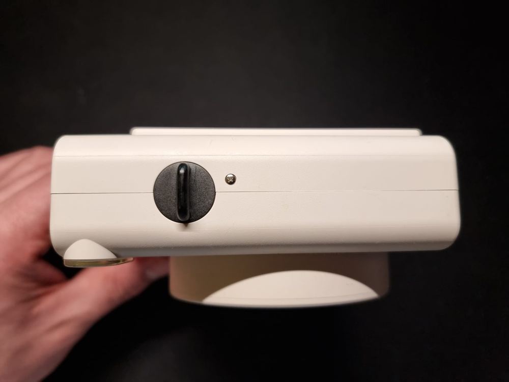
Turn the camera upside down and remove the three screws along the bottom seam. Then remove one screw on each side of the camera, next to the strap lugs. Five screws in total.
Step 3 – Release the film-exit cover
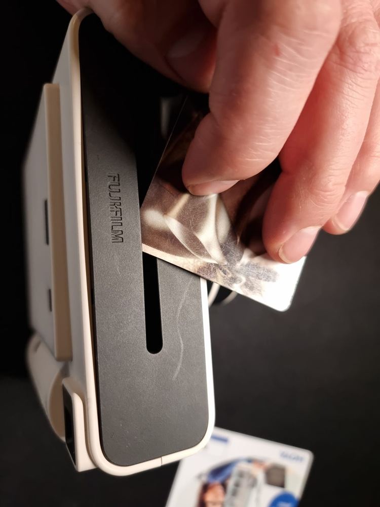
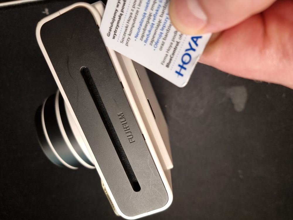
The dark-grey cover with the FUJIFILM logo and the film-exit slot sits on the top of the camera and is held only by clips. Slide a thin plastic card into the gap between the cover and the housing. Work it along all four sides until the clips release, then lift the cover off.
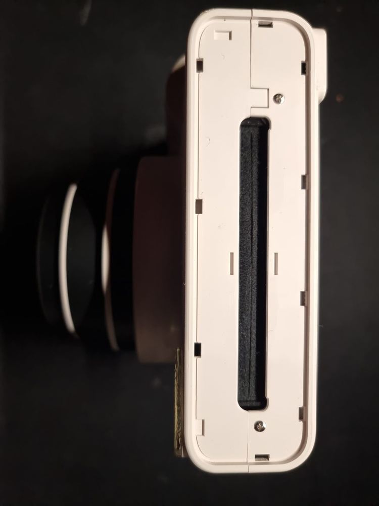
Under the cover there are two more screws, one at each end of the film-exit slot. Remove both.
Step 4 – Separate the rear shell
Pull the rear shell (with the film door) away from the front shell, starting at the side seam. Ease the clips apart with a plastic spudger rather than force. The rear shell comes off and exposes the film chamber of the inner chassis.
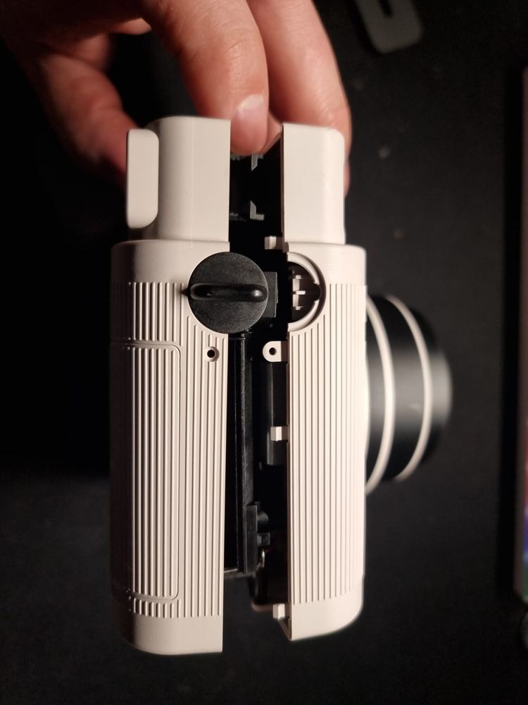
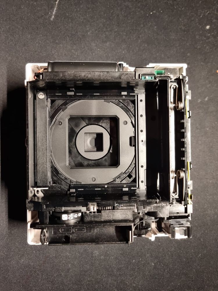
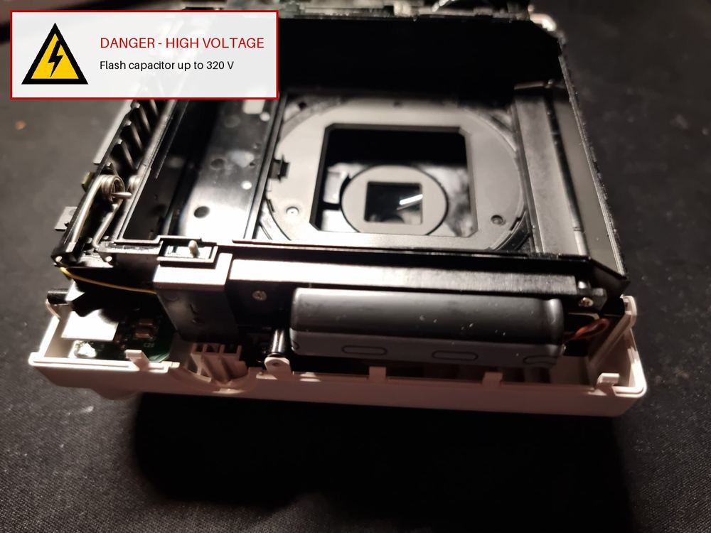
Step 5 – Discharge and remove the flash capacitor
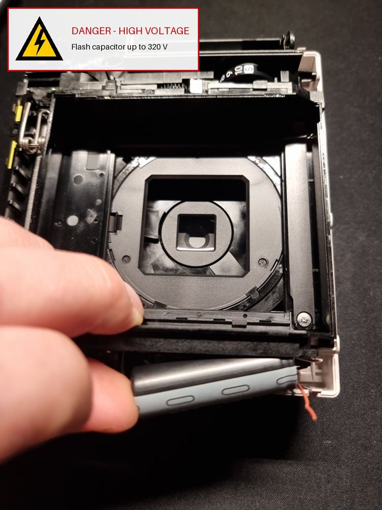
The flash capacitor lies across the top of the chassis, above the film-exit rollers, in a black rubber sleeve.
Cut both capacitor leads with flush cutters, close to the capacitor body. Leave the wire ends on the board side as long as possible and insulate them. Pull the capacitor out of its sleeve; it is a 300 µF / 320 V photo-flash type and is not needed again.
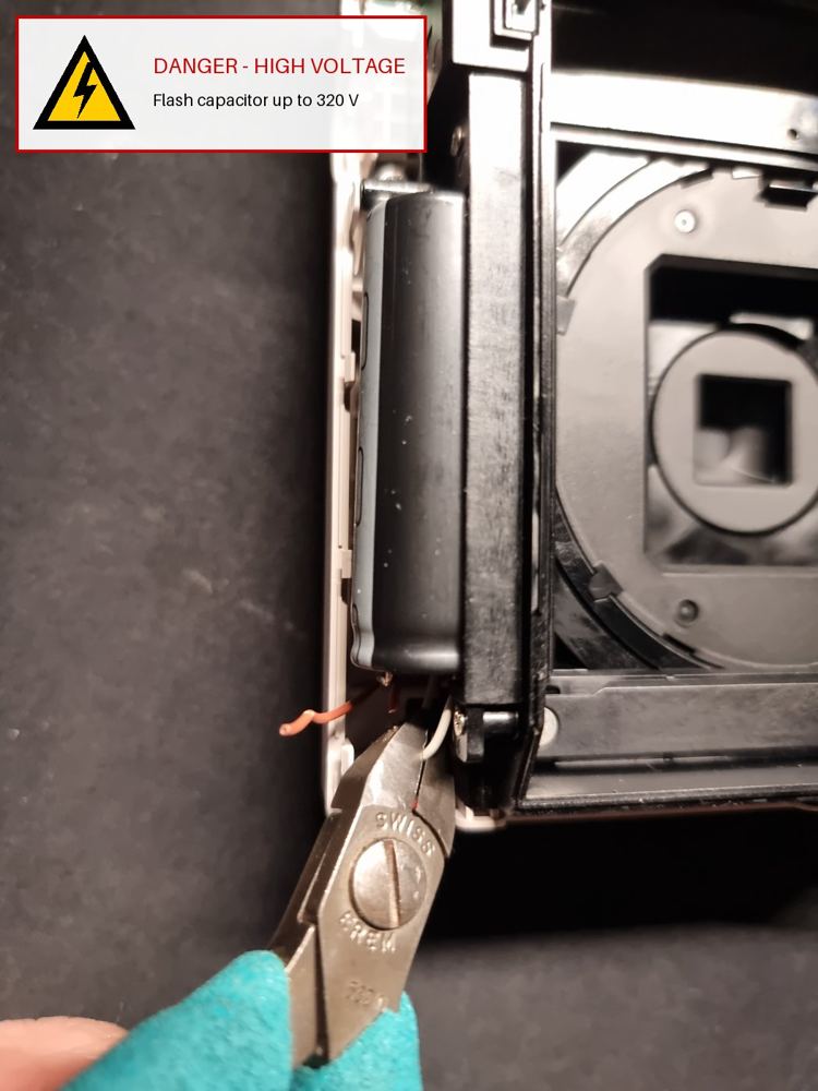
Step 6 – Take the chassis out of the front shell
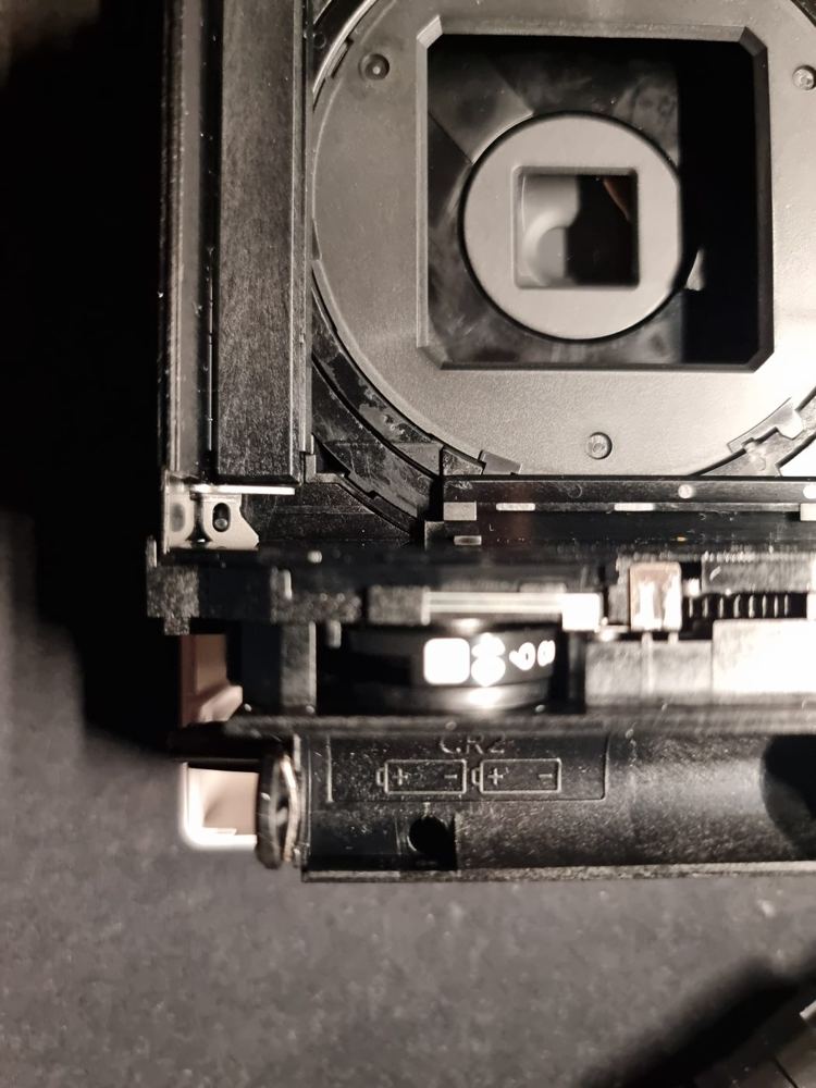
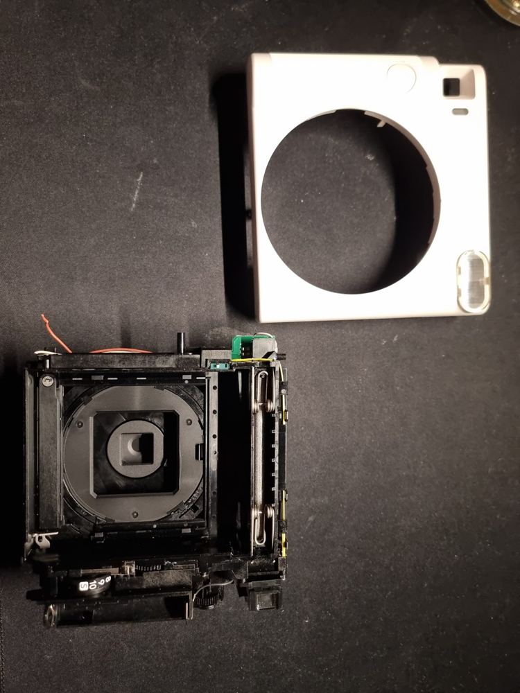
Remove the screw in the lower corner of the chassis, next to the CR2 battery compartment. Lift the complete chassis out of the front shell. The front shell (with the lens ring opening and viewfinder window) comes away on its own.
Step 7 – Disconnect the main board
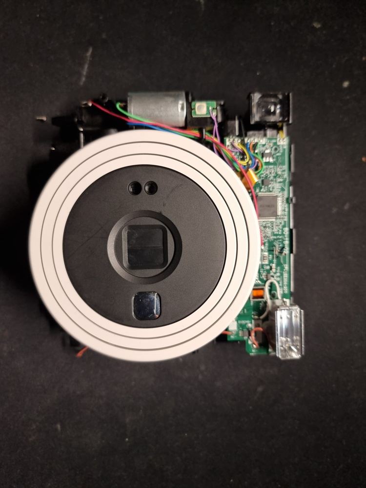
With the chassis lens-side up you see the lens barrel, the main board on the right, the drive motor at the top and the flash unit at the bottom right. Photograph the wiring before you desolder anything, so you can trace every wire later.
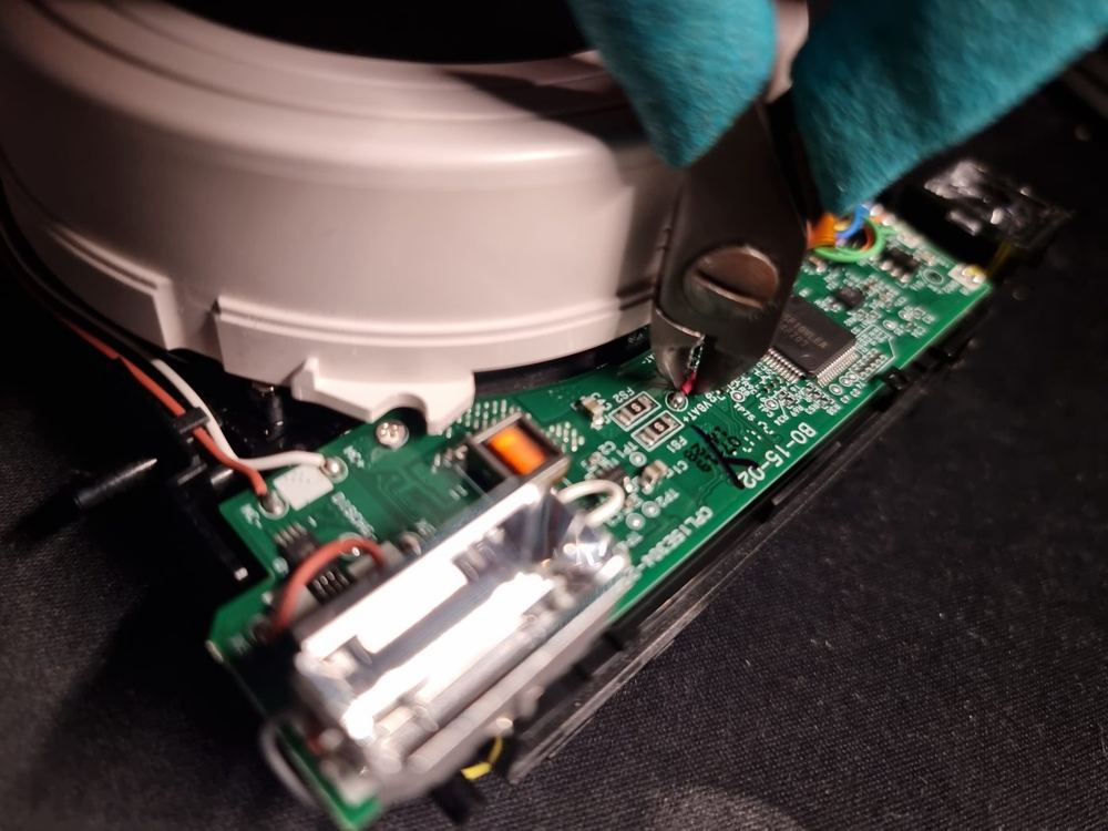
- Cut the battery lead at the BAT+ pad of the main board.
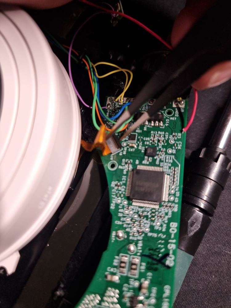
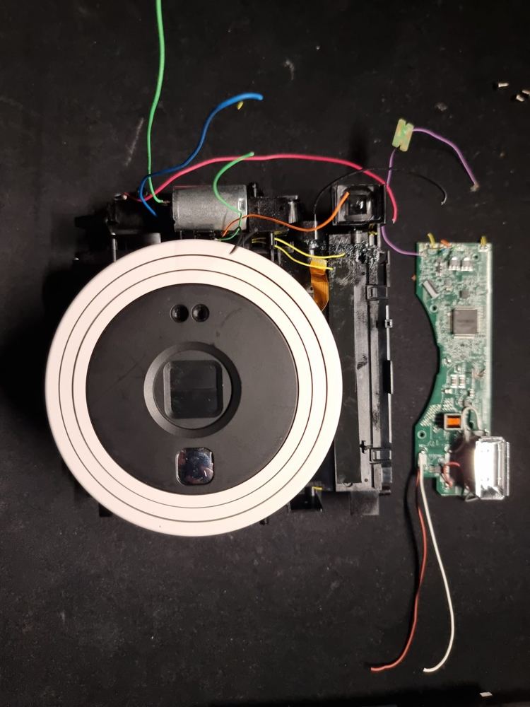
- Desolder the remaining wires and the lens flex cable from the board, using flux and solder wick.
- Free the board from its plastic hooks and lift it away from the chassis.
Step 8 – Remove the lens barrel
Grip the lens barrel by its outer white ring and rotate it until it unlocks from the chassis bayonet. Lift the barrel straight out together with its flex cable. The chassis now has an open square aperture in front of the film.
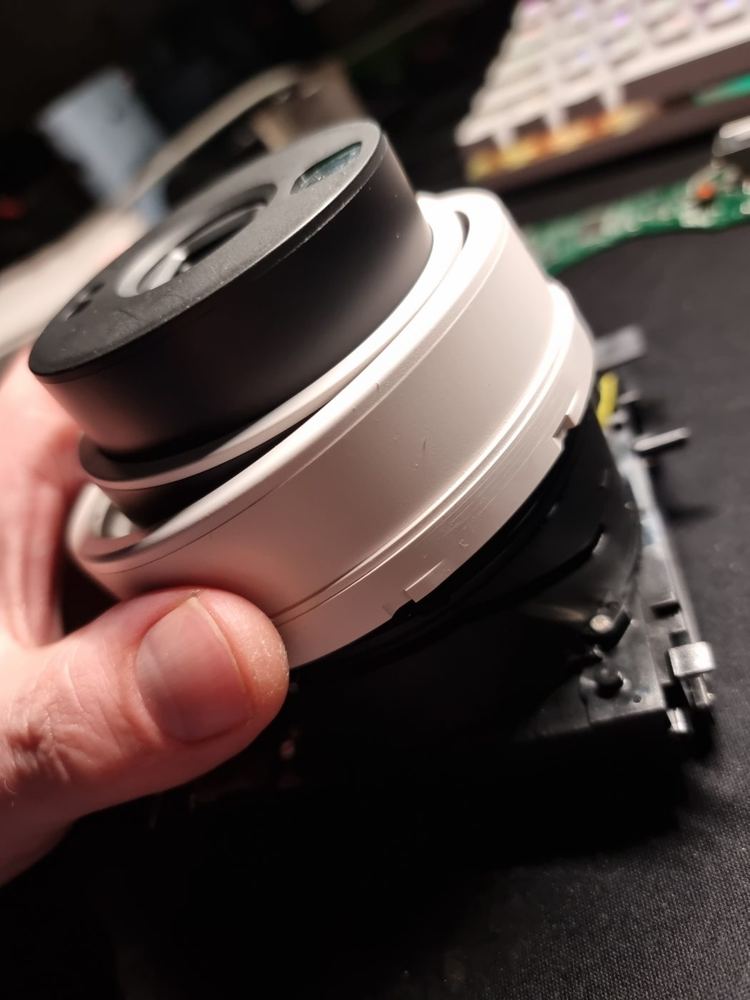
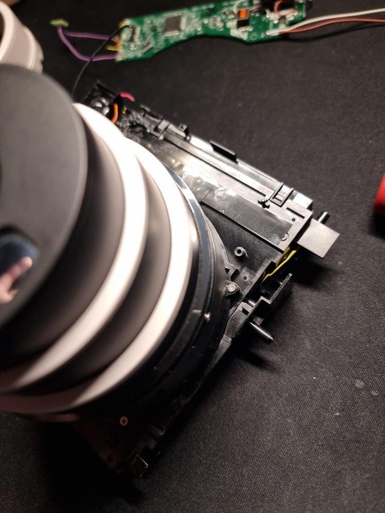
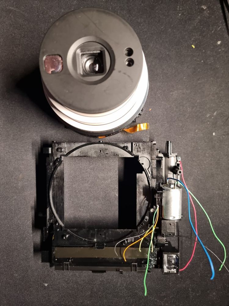
Step 9 – Clean up the chassis
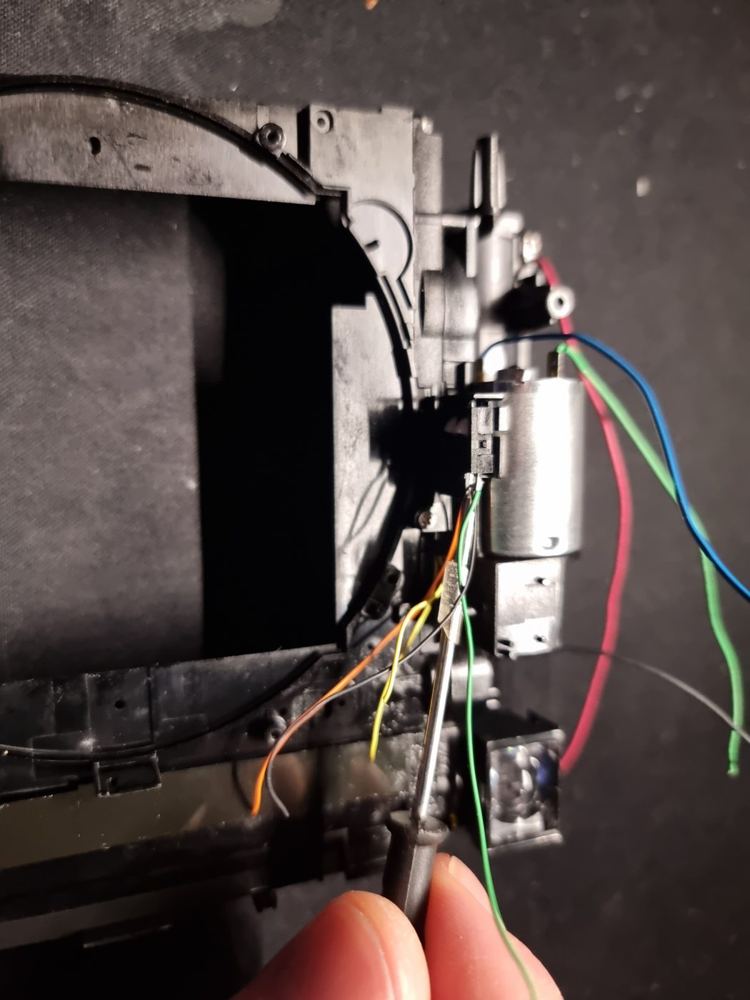
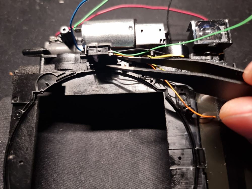
Remove the small screw next to the motor gearbox, then use tweezers to pull the remaining loose wires out of their routing channels around the aperture. Keep the motor, gear train and viewfinder block on the chassis: they are reused.
Step 10 – Housing parts after disassembly
The rear shell, front shell and film-exit cover are left after disassembly. Keep them clean and set them aside for Part 2.
What to keep for Part 2
| Part | Keep? |
|---|---|
| Inner chassis with motor, gear train, film-exit rollers and viewfinder block | Yes |
| Battery compartment with its red and black wires | Yes |
| Rear shell with film door | Yes |
| Front shell | Yes |
| Film-exit cover (FUJIFILM) | Yes |
| All screws, sorted by step | Yes |
| Main board with flash unit | No – replaced by the eject button |
| Lens barrel with flex cable | No |
| Flash capacitor (300 µF / 320 V) | No – dispose of as electronic waste |
Part 2: turn the stripped SQ1 into an RB67 back
Part 2 covers steps 11–20: fitting the M3 nuts, gluing the adapter in its jig, wiring the eject button, fitting the four adjustment screws and setting the fit on the RB67. Every step is illustrated with renders of the 3D models. It comes with the printable files.